Our Focus: Connecting You to Your Data


Webinar
Zones and Conduits for ICSYour Industrial Application is a Target: Use a standards-based approach to provide network segmentation to increase your security posture.
Discover effective strategies for enhancing your application’s security posture through the implementation of security models like zone and conduits and the importance of implementing a defense in depth strategy for your industrial application.
INDUSTRIES WE SERVE
Renewable Energy

Renewable Energy
Wind, solar, and hydro energy producers need to reliably scale operations, and become more dependable and cost-efficient. Red Lion products securely, and reliably, provide the ability to remotely Access, Connect, and Visualize data from the most extreme locations, improving preventative maintenance efficiency.
Factory Automation

Factory Automation
Manufacturing operations need real-time data visibility that drives productivity since minimizing downtime has significant cost implications. Red Lion's secure and reliable Access, Connect, and Visualize products provide critical insights into operational activity to increase uptime and productivity.
Oil & Gas

Oil & Gas
Oil and gas companies around the globe require uninterrupted production of critical resources, whether in the desert, ocean, or ice fields. Red Lion offers rugged products with IECEx certification to access, connect and visualize data across remote oil and gas applications.
Power & Utilities
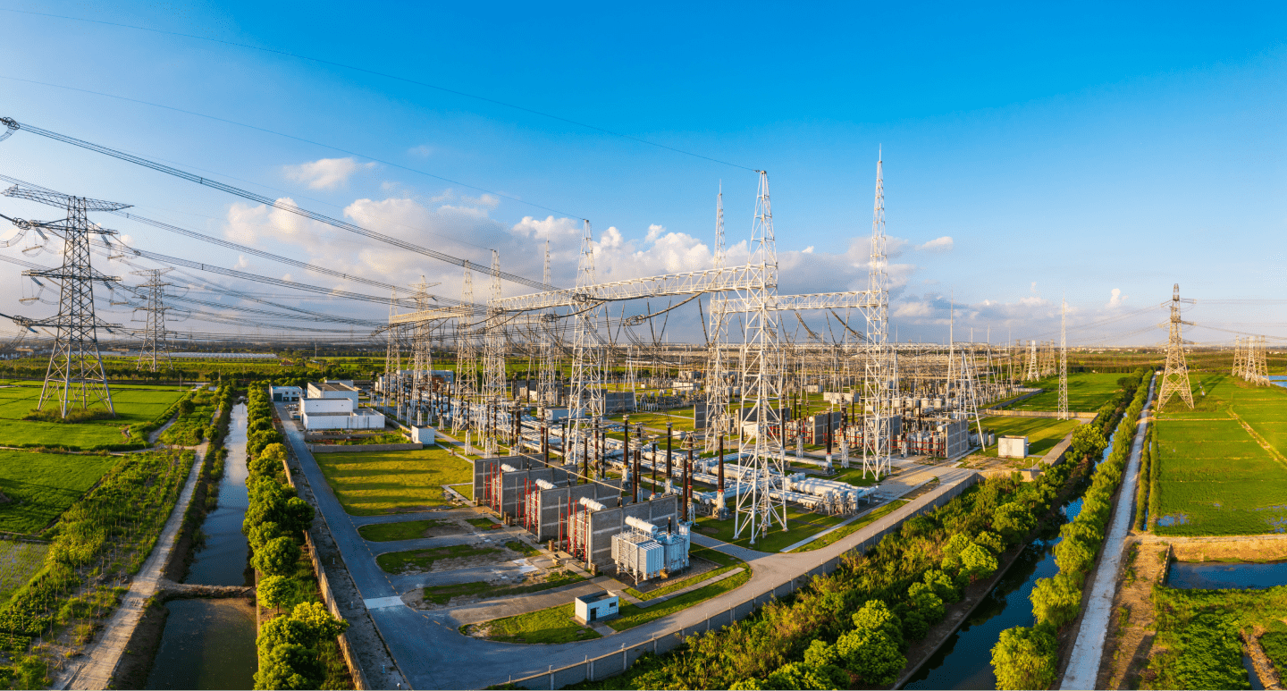
Power & Utilities
Power and utility companies require high-capacity redundant networks to ensure continuous operations in extreme environments. Red Lion provides rugged, secure, reliable products to Access, Connect, and Visualize data for optimal performance.
Transportation

Transportation
Transportation systems rely on information to ensure data and operations keep moving. Red Lion's Access, Connect and Visualize products deliver critical intelligence and communications.
Water & Wastewater
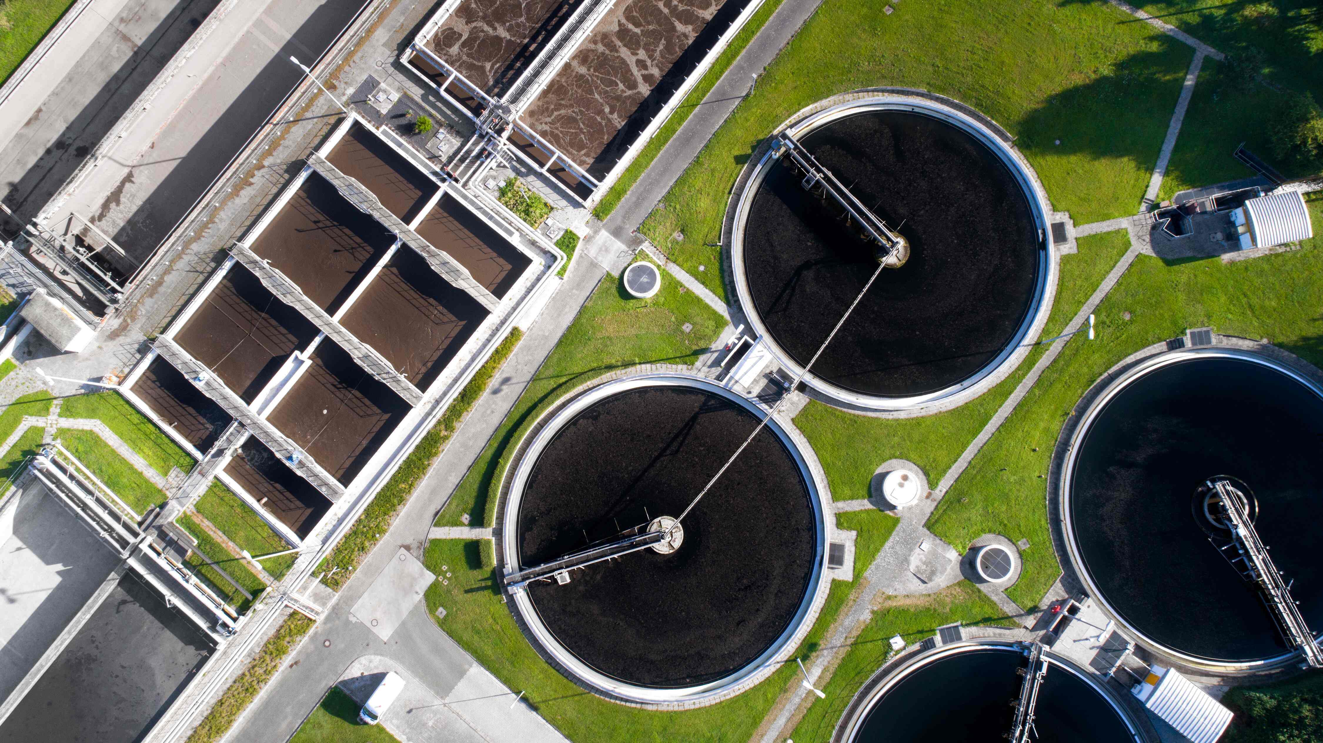
Water & Wastewater
The water and wastewater industry faces pressures to retrieve data from old and new devices and protect against security breaches. Red Lion's products help to securely Access, Connect, and Visualize data without having to overhaul the entire operation.
Renewable Energy
Wind, solar, and hydro energy producers need to reliably scale operations, and become more dependable and cost-efficient. Red Lion products securely, and reliably, provide the ability to remotely Access, Connect, and Visualize data from the most extreme locations, improving preventative maintenance efficiency.
Factory Automation
Manufacturing operations need real-time data visibility that drives productivity since minimizing downtime has significant cost implications. Red Lion's secure and reliable Access, Connect, and Visualize products provide critical insights into operational activity to increase uptime and productivity.
Oil & Gas
Oil and gas companies around the globe require uninterrupted production of critical resources, whether in the desert, ocean, or ice fields. Red Lion offers rugged products with IECEx certification to access, connect and visualize data across remote oil and gas applications.
Power & Utilities
Power and utility companies require high-capacity redundant networks to ensure continuous operations in extreme environments. Red Lion provides rugged, secure, reliable products to Access, Connect, and Visualize data for optimal performance.
Transportation
Transportation systems rely on information to ensure data and operations keep moving. Red Lion's Access, Connect and Visualize products deliver critical intelligence and communications.
Water & Wastewater
The water and wastewater industry faces pressures to retrieve data from old and new devices and protect against security breaches. Red Lion's products help to securely Access, Connect, and Visualize data without having to overhaul the entire operation.
